
#patch #test #mbes #hydrographic #survey #hydrospatial #roll #latency #pitch #yaw
Technical Explanation
Technical Explanation of Patch Test for MBES
The process of conducting a Patch Test for Multi-Beam Echosounders (MBES) is critical in ensuring the accuracy and quality of hydrographic surveys. This document will provide a comprehensive overview of the Patch Test, including its definitions, instrumentation, calibration, geodetic frameworks, datums, data processing workflows, and real-world applications.
Definitions
A Patch Test is utilized to calibrate the attitude sensors of an MBES system. The test focuses on assessing the roll, pitch, and yaw performance of the transducer to minimize errors in depth measurements. Accurate measurements are vital for navigation, seabed mapping, and resource exploration.
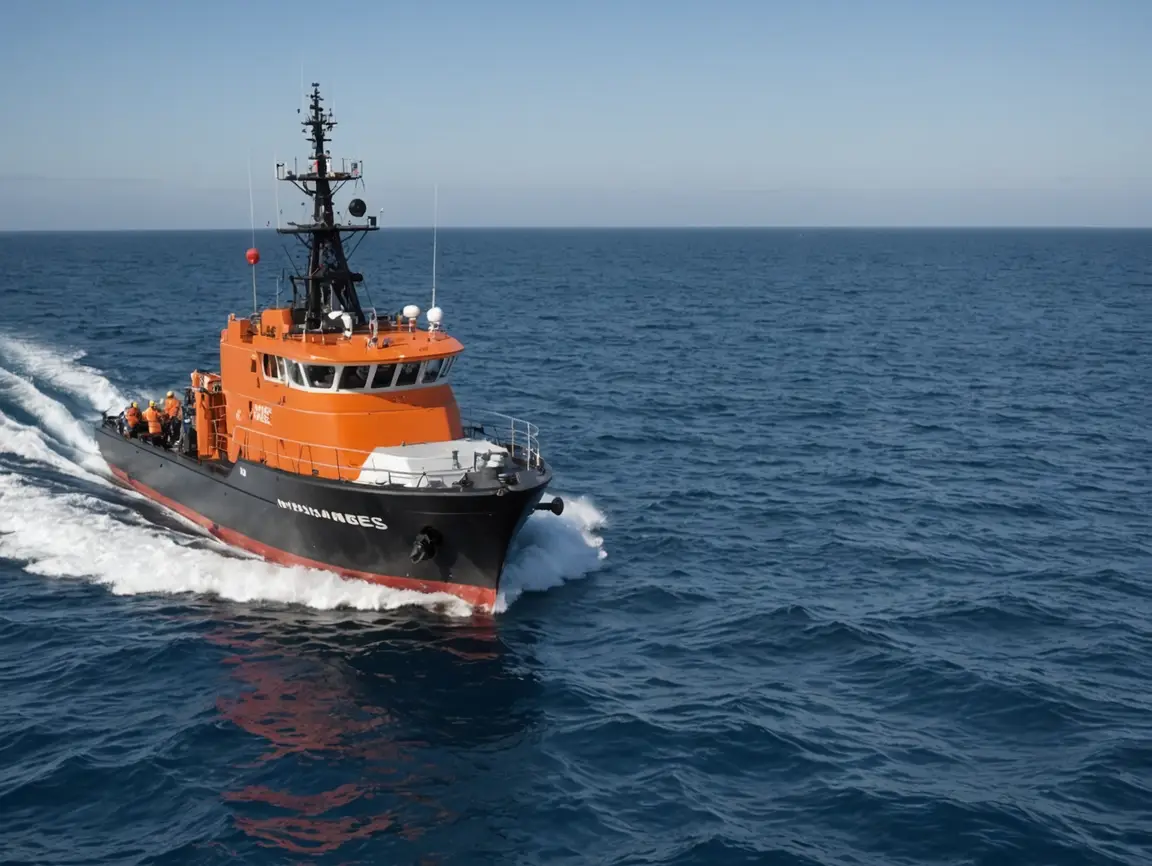
Instrumentation and Setup
- Survey Vessel: Equipped with a GPS antenna and an MBES transducer.
- MBES (Multi-Beam Echosounder): Emits sound waves to measure the depth of water and produce a detailed map of the seafloor.
- GPS Antenna: Provides precise positioning data to synchronize time and ensure accurate referencing of survey data.
Calibration
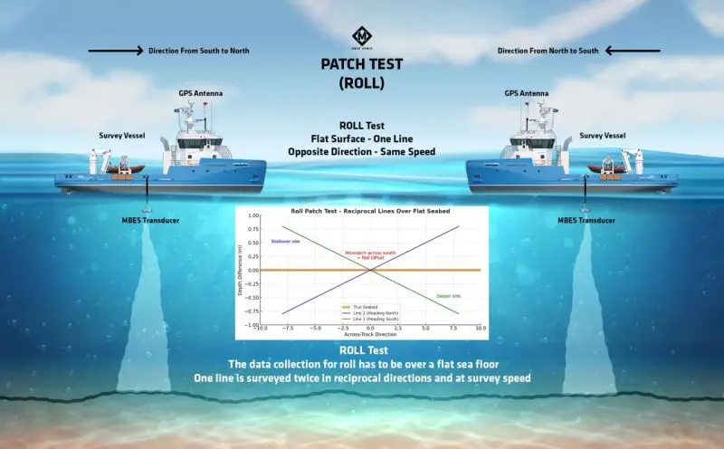
Calibration is crucial for bias correction in the sensor measurements. The Patch Test uses reciprocal lines over a flat surface to verify the performance of the transducer. The tests should be performed in opposite directions at the same speed to effectively analyze the data.
Geodetic Frames and Datums
Proper geodetic frameworks are essential in hydrographic surveying. The relevant datums include:
- Lowest Astronomical Tide (LAT): A reference point used in hydrographic surveying.
- Mean Sea Level (MSL): Average level of the sea surface used as a base for elevation measurements.
Time Synchronization
Accurate time synchronization between the GPS and MBES systems is vital for aligning position data with depth measurements. This ensures that spatial and temporal elements of the survey are coherent.
Data Processing Workflows
The data processing workflow involves the following steps:
- Data Acquisition: Collecting raw data from the MBES during the Patch Test.
- Data Cleaning: Removing any anomalies or errors detected in the acquired data.
- Georeferencing: Aligning data with the correct geodetic reference framework.
- Quality Assurance/Quality Control (QA/QC): Implementing checks to validate data integrity.
- Data Analysis: Interpreting results to determine the effectiveness of the calibration.
Quality Assurance and Uncertainty
QA/QC processes are essential to validate the accuracy and reliability of the data obtained from MBES. Sources of uncertainty must be identified and minimized, including sensor noise and environmental factors, to ensure that the survey results are trustworthy.
Real-World Applications
Patch Testing is foundational in various hydrographic and geospatial applications, including:
- Maritime navigation and safety.
- Environmental monitoring and marine biodiversity assessment.
- Coastal management and infrastructure development.
- Resource exploration and underwater construction.
Conclusion
The Patch Test for MBES is an indispensable procedure that ensures the accuracy and reliability of hydrographic survey data. Understanding the detailed processes involved in the Patch Test enhances the effectiveness of hydrographic practices and contributes to the broader field of geodesy.
System Geometry & Terminology
- Lever arms: 3D offsets (X, Y, Z) from the vessel reference point (VRP) or common reference origin to sensors (GNSS antenna, IMU/INS, MBES head, motion sensor). Measure to centimeter accuracy and sign them using a consistent right-handed vessel frame (X fwd, Y starboard, Z down unless your project specifies Z up).
- Boresight angles: Small rigid-body rotations between the motion sensor frame and the sonar head frame: roll (φ), pitch (θ), and yaw/heading (ψ). Patch testing estimates these.
- Latency (τ): Time offset between position/attitude and sonar ping time. Even tens of milliseconds can cause along-track position errors.
- Waterline offset: Vertical distance from VRP/sensor to waterline; required for precise heave/ellipsoid height reductions.
Pre-Test Prerequisites
- Complete a thorough mount survey (lever arms, initial boresight from mechanical alignment).
- Set a clear sign convention and units (degrees vs radians; Z positive up or down) that match your processing package.
- Establish a reliable time source (GNSS PPS/Time), and ensure all devices are disciplined to it.
- Prepare a SVP plan (sound speed profiles) at start/end and when the water mass changes; enable surface SV monitoring if available.
Test Area Selection
- Flat area (<0.5% slope) with uniform sediment for yaw and general verification.
- Moderate, smooth slope (5–15%) for roll and pitch tests, free of boulders/targets.
- Minimal traffic, low swell/current, and good water-column conditions to reduce decorrelation and refraction.
Recommended Line Plan
- Latency (τ): Run the same straight line in opposite directions past a distinctive feature (wreck, pipeline) or use a shoreline/jetty end. Keep speed constant. The along-track separation of the feature between directions indicates τ:
τ ≈ Δs / vwhereΔs= measured along-track offset of the feature andv= vessel speed. - Pitch (θ): Run upslope and downslope lines along the same track. Depth differences at nadir/near-nadir are dominated by pitch misalignment.
- Roll (φ): Run two lines on a slope, one displaced to port and one to starboard, same heading and speed. Compare outer beams over the same seabed patches; cross-track depth asymmetry indicates roll error.
- Yaw/Heading (ψ): Run a set of parallel lines and one or more crosslines (~90°). Planar mismatches and feature lateral offsets between mainlines vs crosslines resolve yaw.
Computation Notes (Conceptual)
- Latency (τ): Compute from identifiable feature offsets in opposite directions or by minimizing along-track residuals across the line pair:
τ = argmin_τ Σ (s_fwd(t) − s_rev(t+τ))². - Pitch (θ): On along-slope reciprocal lines, minimize depth differences near nadir; many packages solve θ by least-squares over tie points.
- Roll (φ): On a slope, roll bias produces opposite-sign depth errors on port vs starboard outer beams. Solvers minimize cross-track residuals vs beam angle.
- Yaw (ψ): Fit planes to overlapping swaths from intersecting lines; the heading offset that minimizes lateral misfit of features/planes is ψ.
- Apply an iterative approach: estimate τ → θ → φ → ψ, then re-run to refine. Re-grid and re-evaluate after each update.
Sound Speed Strategy
- Acquire SV profiles (CTD/Caribbean, XBT, MVP) bracketing tests and when water mass changes. Use ray-tracing, not constant SV.
- Validate with surface sound speed (SSS) from the transducer face to catch near-surface mismatches.
- Reprocess if residual “smiles/frowns” appear, indicating SVP mismatch.
Vertical Control Options
- Tide-based (LAT/MSL): Use verified tide gauges and zoning models; apply heave correctly (avoid double-applying).
- Ellipsoid-based: Use GNSS heights + geoid/separation model to chart datum. Ensure dynamic draft/waterline corrections are consistent.
Time & Integration
- Verify all sensors use the same epoch and PPS. Confirm NMEA/Network timestamping paths and log latency sources (serial, UDP, file IO).
- Check heave filters (period, stabilization) are appropriate for sea state; heave phase errors can mimic pitch/latency.
Acceptance Criteria & Standards
- After applying patch values, compute crossline statistics. Compare Total Vertical Uncertainty (TVU) to survey order using
TVU = √(a² + (b·d)²)whered= depth. - Typical targets (illustrative): Special Order
a≈0.25 m,b≈0.0075; Order 1aa≈0.5 m,b≈0.013. Ensure your project specification’s values are used. - Horizontal uncertainty should satisfy project/standard (e.g.,
95%within specified meters).
Quality Metrics to Report
- Line-to-line depth residuals (mean, RMS) by beam angle and across swath.
- Feature offsets between reciprocal lines (for τ and ψ checks).
- Plane-fit residuals for intersecting lines.
- Waterline/draft values used and variability during runs.
- SVP usage log and any ray-trace QC plots (beam bending checks).
Common Pitfalls & Remedies
- Wrong sign conventions: Depths worsen after applying values → re-check frames and signs.
- Inadequate slope: Too flat for roll/pitch sensitivity → choose a steeper, smooth slope.
- Swell/turning: Manoeuvres and sea state contaminate heave/attitude → run straighter, calmer windows.
- SVP mismatch: Smiles/frowns persist → refresh SVP and re-raytrace.
- Inconsistent speeds: For τ tests maintain speed; variable speed biases Δs/v estimates.
Repeatability & Re-Test Triggers
- Re-run patch after any mechanical change (mount, cable, transducer service) or sensor relocation.
- Schedule periodic verification (e.g., weekly on long projects) and after significant sea state changes.
Deliverables Checklist
- Final lever arms and boresight (φ, θ, ψ) with signs, units, confidence.
- Latency τ (ms) and method used.
- Line plan, run times, speeds, SVP list, environmental notes.
- Statistical crossline report, plane-fit residuals, TVU comparison to specification.
- Screenshots/plots demonstrating pre- vs post-patch improvements.
Software-Agnostic Workflow Hints
- Import raw navigation, attitude, MBES, SVP. Verify time alignment and lever arms.
- Ray-trace with current SVP; apply draft/waterline and heave correctly.
- Run patch solvers for τ → θ → φ → ψ. Apply updates iteratively.
- Re-grid; evaluate residuals; repeat if needed until residuals and TVU pass.
- Lock values; propagate to project configuration; document.
Abbreviated Math Intuition (Non-rigorous)
- Latency:
τ ≈ Δs / v(feature shift over speed). - Roll effect: depth error grows with beam angle β approximately like
Δz ∝ R · sin(β) · φfor small φ. - Pitch effect: near-nadir depth bias on reciprocal along-slope lines changes sign with direction.
- Yaw effect: lateral displacement of features between mainlines and crosslines; minimize via ψ.
Minimal Field SOP (Quick Reference)
- Complete mount/lever-arm survey and set frames/signs.
- Collect SVP; verify time sync; calm sea if possible.
- Run τ pair → run θ pair (upslope/downslope) → run φ pair (port/starboard on slope) → run ψ crosslines.
- Process and solve parameters in that order; iterate once.
- Generate crossline report and sign off against specification.
Suggested References for Further Study
- IHO Standards for Hydrographic Surveys (S-44), TVU framework and survey orders.
- Manufacturer application notes for specific MBES models (patch testing procedures and recommended slopes).
- Hydrographic survey QA/QC guides discussing crossline analysis, plane fitting, and uncertainty budgets.
“`